
The most widespread are fuel battery systems with hydraulic accumulators. Accumulators are made in the form of separate containers or as a whole with a high-pressure pump or nozzle.
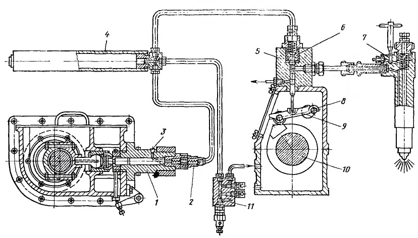
An example of a fuel system with a battery in the form of a tank is the injection system of the main marine diesel Doxford. A high-pressure pump 1 with an eccentric drive supplies fuel through two automatic injection valves 2 of the ball type into a container 4, in which a pressure of 420-490 MPa is maintained. The pressure in the container is monitored using a manometer connected to box 11, which contains shut-off, safety and drain valves.
The fuel enters the pump through the suction valve and the inlet port 3. The fuel supply to the cylinder is controlled by throttling at the suction by changing the flow area in the valves. From the storage tank, the fuel flows to the metering device 5 through two poppet valves 6, controlled by the cam washer 10 and the lever 9, and then to the nozzle 7.
Elements of accumulator fuel battery systems have design features. In high pressure pumps, the number of sections does not depend on the number of diesel cylinders and can be different. One section can serve one, two, three and rarely four cylinders. The operation of the pump is usually not synchronized with the operation of the diesel engine, since neither the speed, nor the fuel consumption, nor the phases of the process are determined by the operation of the diesel engine.
The pushers of these pumps receive movement from eccentrics or cams of the shafts, which are kinematically connected to the diesel crankshaft. Pumps can be regulated or non-regulated. In the latter case, pressure reducing valves are installed on the accumulator, which act as pressure regulators. In variable speed pumps, the fuel flow rate is changed by means of an oblique edge of the plunger or throttling on the filling line.
The tanks are used to store the fuel pumped by the system pumps. The pressure in the tanks must be sufficient to ensure high-quality atomization of the fuel supplied by the nozzles into the diesel combustion chamber. The pressure ranges from 40 to 60 MPa. In most cases, one large-volume container is installed on one diesel engine, from which the injectors of all cylinders are fed.
In order to improve the reliability of operation in some diesel engines, in addition to the total capacity - the accumulator, individual accumulators are additionally installed after each section of the high-pressure pump. Such a system ensures the most reliable operation of the diesel engine, since in case of failure of one section, the rest will continue to supply fuel to the working diesel cylinders. A scheme is also used in which the container and the pump serve a group of two or three cylinders.
By design, the containers are thick-walled vessels equipped with the necessary fittings. They not only collect fuel, but also dampen fuel fluctuations that occur during the operation of the system, and also smooth out the pulsations of the fuel pumps.
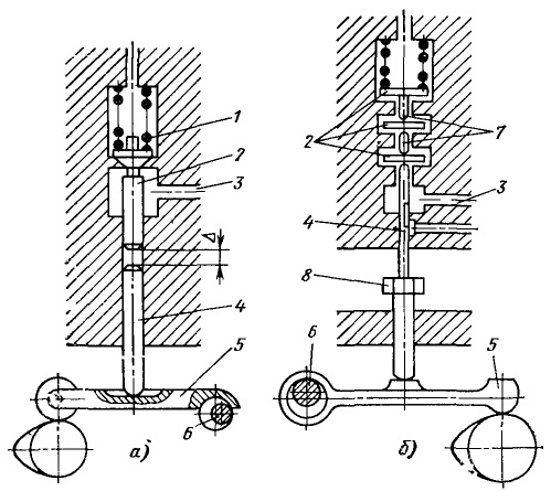
Diagrams of two dosing devices are shown in the figure. When the washer runs onto the roller of the lever 5 (Fig. A), the latter acts on the pusher 4 and raises it up. After choosing the gap, the pusher rests against the end of the valve 2, loaded with spring 1, opens it and the fuel from the injection fuel line flows through channel 3 to the injector.

The dosing device (Fig. B) works as follows. When the cams of the washer run onto the lever 5, mounted on the eccentric roller 6, the cylindrical pusher 4 rises and opens the plate valves 2 with the help of the crosspieces 7. The fuel, passing through the throttling section under these valves, enters channel 3 leading to the nozzles. Once the plate valves are seated on the seat, the end of the tappet breaks away from the lower plate valve and then connects the fuel injection line to the cutoff line, unloading it and providing a clear cutoff at the end of injection.
The dosing of the fuel supplied to the cylinder is carried out by an eccentric roller 6. By turning the eccentric roller, the moments of opening and closing of the plate valves, and, consequently, the cyclic supply, are changed. The eccentric roller is under the influence of an all-mode adjuster. The feed to the individual cylinders is adjusted with bolts.
Nozzles are used in these battery battery systems systems, automatic and mechanically driven. When using mechanically controlled nozzles, the dosing device is not installed. The injector drive is kinematically connected to the diesel crankshaft and is under the influence of the regulator. The complexity and cumbersomeness of this drive, the need for careful sealing of the reciprocating needle, the relatively short service life of this unit prompts to give preference to automatic nozzles operating from metering distributors.
Comments
Post a Comment